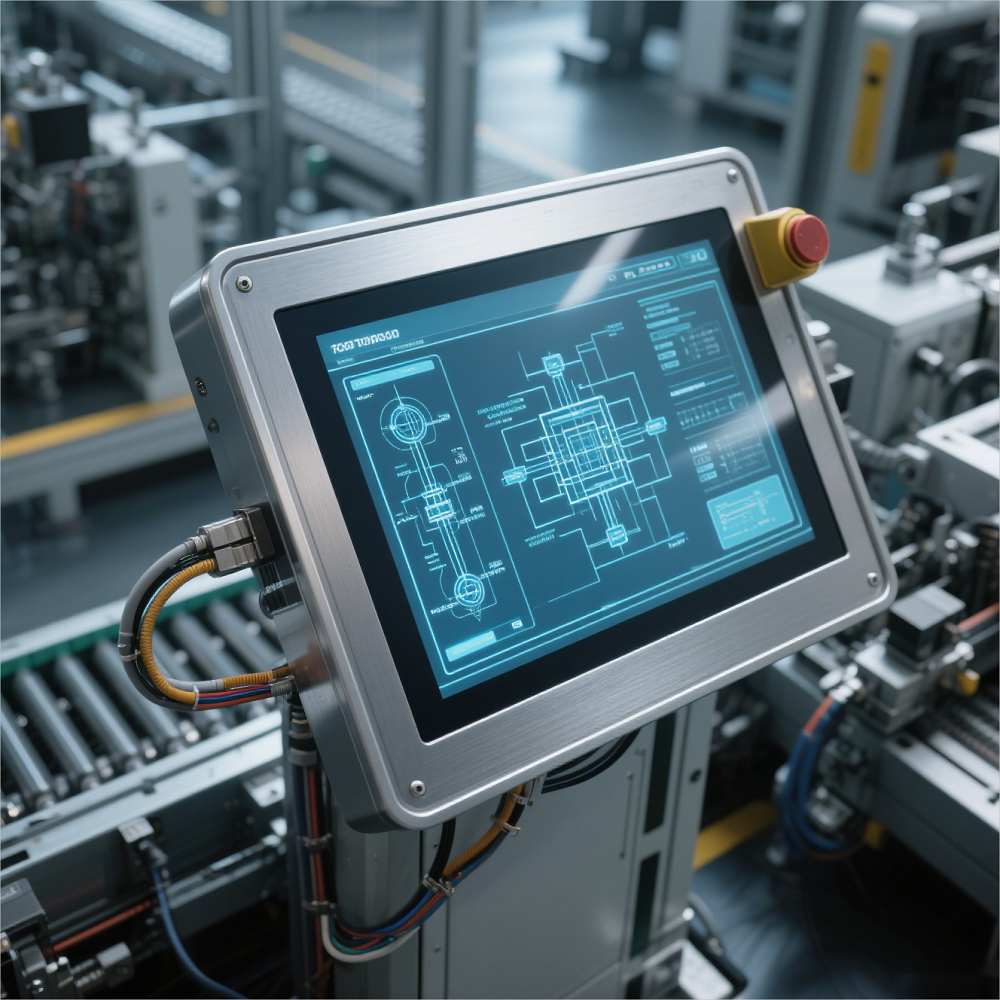
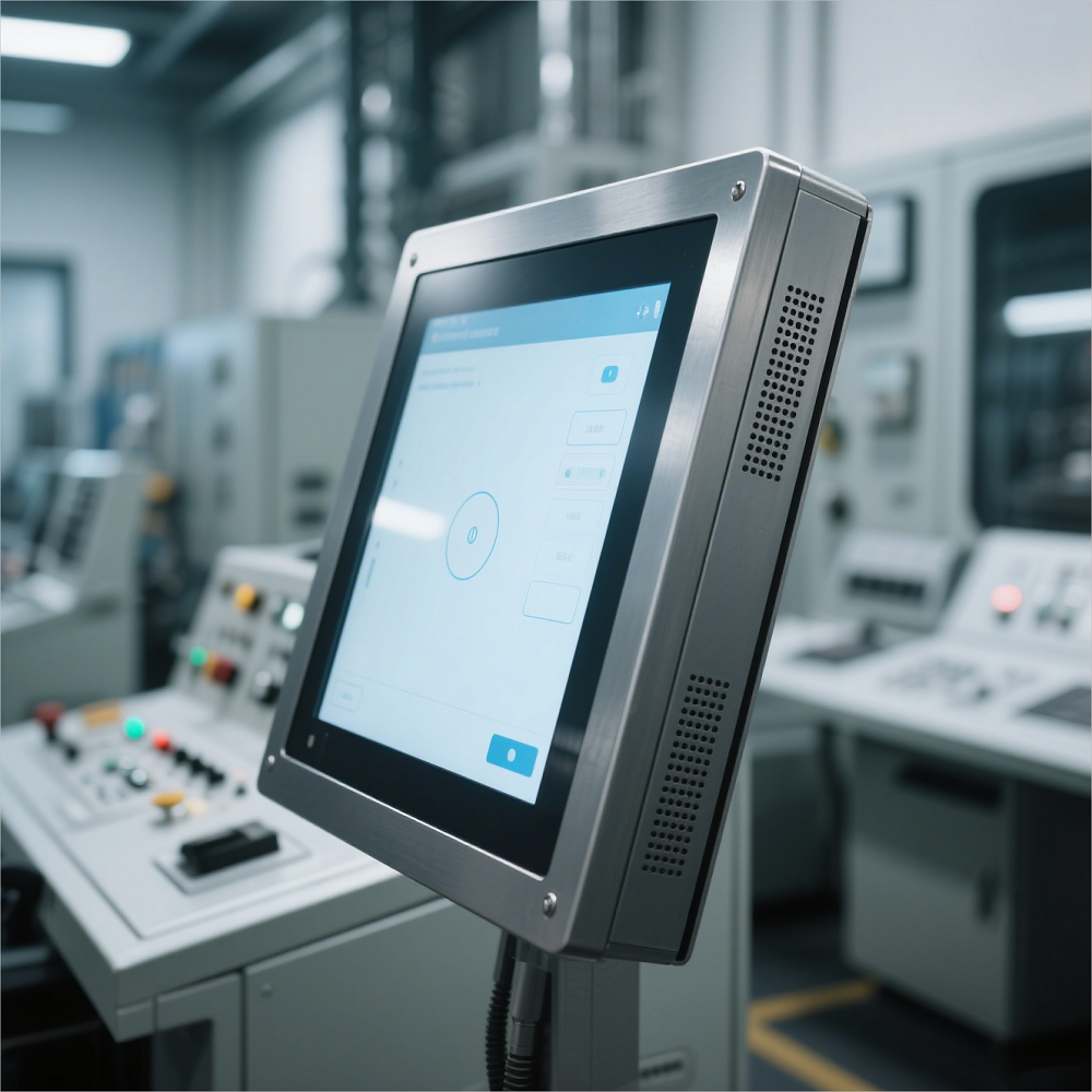
As the core equipment of human-computer interaction, industrial touch screens need to operate stably for a long time in harsh industrial environments. Their reinforcement design and reliability improvement need to be optimized from four dimensions: structural design, material selection, environmental adaptability, and electrical safety. The following are specific plans and implementation points:
I. Structural design reinforcement: Improve shock and vibration resistance
Modular frame design
Metal skeleton reinforcement: Use aluminum alloy or stainless steel one-piece frame, optimize structural strength through finite element analysis (FEA), and ensure that it can withstand more than 10G shock (in compliance with IEC 60068-2-27 standard).
Shock-absorbing installation method: Embed silicone shock-absorbing pads or spring screws between the touch screen and the device housing to reduce vibration transmission efficiency (such as attenuating vibration acceleration to less than 30% of the original value).
Protection level improvement: The housing design must meet IP65 and above (dustproof and waterproof), and the interface uses a threaded locking or snap-on sealing structure to prevent liquid infiltration and short circuit.
Optimization of touch screen fixing method
Four-point support + edge buffer: Use high-strength screws to fix the touch screen to the four corners of the frame, and paste 3M VHB™ (super sticky foam tape) on the edges to disperse stress and prevent glass breakage.
Suspended installation: For large-size touch screens (such as 15 inches or more), elastic support columns are used to achieve a "suspended" effect to avoid deformation caused by thermal expansion and contraction or mechanical stress.

II. Material selection: Enhanced weather resistance and corrosion resistance
Surface material upgrade
Tempered glass: Use chemically strengthened glass (such as Corning Gorilla Glass), with a surface hardness of 9H (pencil hardness test), and scratch resistance is 5 times higher than ordinary glass.
Anti-reflective coating: AR (anti-reflective) film is plated on the glass surface to reduce the reflectivity from 8% to below 1%, reducing glare interference under strong light.
Anti-fingerprint coating: Use nano-level hydrophobic and oleophobic coating (such as AF coating) to reduce fingerprint residue by 70% and reduce the frequency of cleaning.
Corrosion-resistant treatment of structural materials
Aluminum alloy anodizing: The metal frame is hard anodized (thickness ≥ 25μm), and the salt spray resistance time exceeds 1000 hours (in accordance with ASTM B117 standard).
Stainless steel passivation: 316L stainless steel parts are pickled and passivated to form a dense oxide film to prevent chloride ion corrosion (suitable for marine or chemical environments).
III. Enhanced environmental adaptability: Coping with extreme temperature, humidity and electromagnetic interference
Wide temperature working design
Temperature compensation circuit: The temperature sensor is integrated in the touch screen controller to dynamically adjust the touch sensitivity according to the ambient temperature (such as the error ≤5% in the range of -20℃ to 70℃).
Heating/cooling module: For ultra-low temperature environments (below -40℃), a flexible electric heating film (power density ≤0.1W/cm²) is attached to the back of the touch screen to prevent the liquid crystal material from solidifying.
Dustproof and waterproof sealing
Double-layer sealing structure: "Silicone ring + waterproof glue" is used between the touch screen and the shell to ensure that there is no leakage under a water pressure of 100kPa (1 meter water depth).
Breathable valve design: Install a GORE™ breathable valve on the housing to balance the internal and external pressure difference (to prevent condensation) and block dust and water vapor (protection level IP67).
Electromagnetic compatibility (EMC) optimization
Shielding layer design: Paste copper foil or conductive foam on the back of the touch screen to form a Faraday cage effect to suppress electromagnetic interference in the 100MHz-3GHz frequency band (in compliance with IEC 61000-4-3 standard).
Filter circuit: Add an X/Y capacitor combination at the power input to attenuate the conducted interference to ≤40dB (150kHz-30MHz frequency band).

IV. Improved electrical safety and reliability
Overvoltage and overcurrent protection
TVS diode: Connect a 15kV withstand voltage TVS diode in parallel at the USB/RS232 interface to prevent static electricity or lightning from damaging the circuit.
Resettable fuse: Connect a PPTC (polymer positive temperature coefficient) device in series in the power line, which automatically disconnects when overcurrent occurs and automatically recovers after the fault is eliminated.
Data transmission stability
Differential signal transmission: RS485 or CAN bus is used for long-distance (>5 meters) connection, and common mode noise is offset by differential signal (bit error rate ≤10⁻¹²).
Optical fiber interface option: For high electromagnetic interference environment (such as near the inverter), optical fiber communication module is provided to isolate electrical noise.